

Optimising parameters to configure tongue and groove optimisations
Check the box to set tongue and groove mode
Enter values for the length of the tongue and depth of the groove
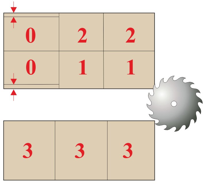
The ‘Tongue and groove’ information box is used to define part positions on the board (see the ‘Part’ group of information boxes). Parts can be configured to be at the tongue (front/bottom) edge, groove (rear/top) edge, tongue and groove (top and bottom) edges or offset from both edges (i.e. no tongue or groove). To configure the part positions the following values should be used: -
0 = part with no tongue or groove edge
1 = part with tongue edge
2 = part with groove edge
3 = part with tongue and groove edges
Parts with a tongue edge are positioned at the front edge of the board and cannot overlap the groove at the rear.
Parts with a groove edge are positioned at the rear edge of the board and cannot overlap the tongue and the front.
Parts with both a tongue and groove must be the same width as the board
Parts with no tongue or groove are positioned in the middle of the board do not overlap the groove at the rear or tongue at the front.
Notes
- Can also be set as a material parameter at material level
- Rip and recut trim values are ignored and assumed to be zero for tongue and groove
- Parts with no grain set are assumed to be Y grain
- Board orientation settings are ignored and assumed to be lengthways
- Only head offcuts are produced from tongue and groove patterns
|
|