

How the diagram for the edging on a part appears on a label
The 'edging diagram' for each part specifies the sequence and method for applying edging, for example, whether the edging is mitred at a corner or flush.
At the Designer screen:-
● Select: Parameters - Edit
The screen shows the Form and Label parameters dialog
● Select the Edging diagram tab
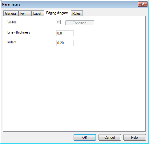
Work through the parameters and check or set the values.
For details of each item see the topics below.
The diagram is drawn directly on the label and uses the full label size to show the edging. The diagram does NOT match the scale of the part as its purpose is to show clearly the edging method for the part.
The 'Indent' specifies how the diagram lines are positioned on the label. Make sure that the other items on the label are also within the area specified by the indent so that the diagram does not overlap the other information on the label.
Notes
- There can be different parameter settings for each template if necessary
![]()