
Overview of how to create machining library drawings
To view or create part drawings containing machine instructions select the Machining library option. Use the List box to locate and select a part or use the Navigation buttons to browse through the library.
At the left of the screen is the FUNCTION toolbar area use this to select the type of machining operation and to the right is the drawing area. Click on a button to add a new function to the drawing.
When a function is selected from the toolbar a set of boxes appear at the left - use these to enter the details for each function, such as, X and Y co-ordinates, depth, tool number etc. The boxes vary with each function. The drawing is built up as enter machining operations are added.
To move directly to a machine operation (for example to edit the details) click on the relevant part of the drawing. The current instruction is highlighted.
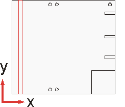
The drawing code and size (if appropriate) are shown at the top of the screen. Here is a drawing with some machining instructions.

The instructions for the vertical drilling at the top of the drawing are as follows.
Function Vertical drill
Description Vertical drill
Back
Layer 2
On/Off
Xstart 350
Ystart Y-15
Xend
Yend
Width 10
Depth 15
Repeat 1
Direction R
Offset
Tool
In some cases the machine instructions are defined by a formula in terms of the dimensions of the part (X,Y) and that not all the properties are used.
The TOOL property can be very useful as it allows for the instructions to be extended by entering extra machining centre instructions which are unique to each type of machining centre.
Drawing Origin - The origin of the drawing is shown by two lines at right angles indicating the x and y directions and the origin. Define any of the four corners of the drawing as the origin but keep the same origin for all drawings. To choose the origin see: Machining centre parameters
Co-ordinates - The co-ordinate system in use (as shown in the example) follows the very common convention of using y for the vertical component and x for the horizontal component. The symbols X Y and Z are used for the variables associated with a part.
X - part length
Y - part width
Z - part thickness
Note that X indicating the part length is different from x indicating the x co-ordinate.
Machining centre parameters - Also set the machining centre parameters to specify the type of machining centre and other general features of your machining operation
- Use the mouse to enter machine instructions. Click on a blank drawing or on an existing machine instruction to begin editing.
- Use the mouse to enter the start or end points or centre point of a groove, circle or arc or use the mouse to copy and move an instruction.
- Right click with the mouse for the options to edit, move, copy and delete instructions.
Notes
- Check System parameters to make sure that data for part drawings and cutting instructions are created.
- On/Off - Most instructions have an On/Off box this determines whether the function or instruction operates or not. If the field is blank or the formula entered evaluates to 1 the instruction is performed; otherwise if a formula evaluates to 0 the instruction is not performed. Individual elements of a contour cannot be switched on and off; the On/Off field applies to the whole of a contour.
- Show all instructions - At the View menu use the option 'Show all instructions' to determine whether the Drawing shows or does not show instructions (e.g. routs) that are Off.