

Settings for each machining drawing
These are the setup values for each drawing.
● Select: File - Drawing properties
The drawing properties dialog is displayed.
● Check or set the values
OK to finish
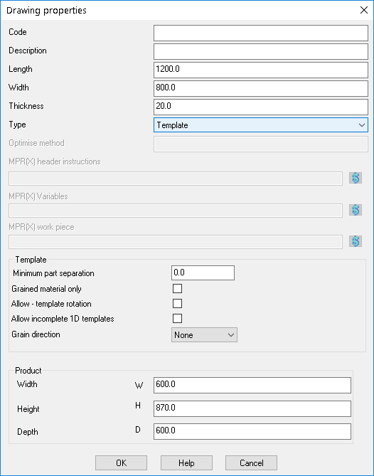
Drawing properties
Part code, part description - part from part library associated with drawing
Type - select drawing, link or template
'Link' defines the drawing as a drawing that can be linked to by other drawings. 'Template' defines the drawing as fixed layout for use with nested patterns.
Optimise method - this works in the same way as Machining centre parameter Optimise method but can be set for each drawing. If this field is left blank the Machining centre parameter is used for that drawing
MPR(X) header instructions - any MPR(X) header items for the drawing
MPR(X) variables - any MPR(X) variable items for the drawing
(These are the same as the Machining Centre Parameters - but apply to each drawing. Only for Homag WoodWop V4+)
Orientation - The orientation of a link within a part. This can be either Top Left, Bottom Left, Top Right or Bottom Right.
MPR(X) Workpiece - information in the '<100' section, for example:-
RNZ="0"
FNX="2.5"
FNY="2.5"
...
This information is typically the X, Y and Z offset for the part but any of the necessary MPR(X) instructions for this section can be set. Enter the instructions separated by a colon, for example:-
RNX="0":FNX="2.5":FNY="2.5"
The X, Y and Z offsets can also be set globally via the Machining centre parameter (WoodWop tools 1 - Offset). If a value is entered in both the machining centre parameters and the machining library, the machining library value takes precedence.
Parameters for Nesting templates
When working with templates for Nesting the following three parameters are used.
Minimum part separation
Grained material only
Allow - template rotation
Allow incomplete 1D templates
Minimum part separation - specifies the gap between the parts for the current template drawing. This must match the router diameter specified in the optimising parameters when the template is used.
Grained material only - if a pattern does not have a grained material the template is not used when creating nested patterns. Set this parameter OFF to force the use of grain match templates for non-grained parts.
Allow template rotation - set whether the template can be placed on a pattern in the rotated orientation.
Allow incomplete 1D templates - When this option is set a one dimensional template no longer needs parts assigned to every position in the template and the nesting template calculations automatically adjust the part positions accordingly.
Grain direction – Specifies the grain direction for the template. If the grain direction is ‘None’ there is no specific grain direction and all parts in a template must have the same grain. If the grain direction is ‘Lengthways’, parts with Y or N grain have the same orientation as the template and parts with X grain are rotated by 90 degrees. If the grain direction is ‘Widthways, parts with X grain have the same orientation as the template and parts with Y or N grain are rotated by 90 degrees.
Product dimensions
The dimension values are used to evaluate any machining instruction on the current drawing that use formulae that refer to the products dimensions, for example:-
The product depth is set to 600 and the product depth field is set to D then =D/2 in a formula will evaluate to half the depth or 300. In a product based optimisation then the actual product dimensions are used.
Notes
- Some parameters are not used (greyed out) if the drawing is a template