

Machining option to define cut-out in a piece
● Select: Function - Cut-out
or
![]() Select
option from the Function Toolbar
Select
option from the Function Toolbar
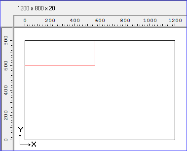

Move the cross hair cursor to the required location
First click - Start
Move to create rectangle
Second click - End
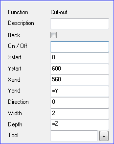
● Adjust the values with the Machining instructions pane at the left
A cut-out can also be entered as a series of grooves but it is often easier to use the cut-out function.
Specify two opposite corners of the cut-out using Xstart/Ystart and Xend/Yend boxes.
Specify the direction the cut is taken in the Direction box. Use the direction to specify whether the generated instructions travel in an anti-clockwise (0) or a clock wise direction (1).
Use the Width box to specify the width of the router path. This is the width of the router path not the width of the complete cut-out.
The depth of the cut-out is specified in the Depth box. Z stands for the part thickness.
For the Cut-out the drawing is always shown as a single line regardless of the actual width of the path.
Use the Tool box to enter the tool number and instructions.
 Click
on the Tool button to enter options via a dialog
Click
on the Tool button to enter options via a dialog
Notes
Machining centres
The default assumes that the co-ordinates specify the centre of the cut-out path.
For some machining centres a special command is available for the Toolbox (RK=) to override this choice.
RK=1 writes RK=WRKL in the MPR(X) file
RK=2 writes RK=WRKR in the MPR(X) file
RK=0 writes RK=NOWRK in the MPR(X) file
If the RK value is not set we write RK=NOWRK in the MPR(X) file.
The setting (<105 \Konturfraesen\) in the WoodWop configuration file: ww40\a1\ww40.cfg is not used.
Saw
The cut-out is defined in the .SAW file in the COT2 line. The coordinates are the outside of the saw blade.
- Bridges are not used and the values are set to 0
- The cut-out is defined by setting the top left and bottom right points.
Each cut-out dimension is as follows:-
- Part item number
- Side (0 = front, 1 = back). Set to 0
- Start of cut-out (X, Y of top left)
- End of cut-out (X, Y of bottom right)
- Length of corner bridge. Set to 0
- Length of intermediate bridge. Set to 0
- Minimum size of intermediate bridge. Set to 0
![]()