

Drawing option for Machining
To draw an arc, at the Machining library:-
- Select: Function – Arc Router
- Choose the method to draw the arc from the sub menu
Or
Choose an arc symbol from the toolbar
The options are:-
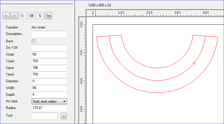
- Start, end, radius
- Start, included, end
- Centre, start, angle
Start, Included, end
This mode allows arcs to be defined by first clicking with the mouse to define a start point, then clicking again to define an included point and then finally an end point. The included point always includes in the arc so positioning it between the start and end point produces an arc with a direction of 0 (< 180 degrees, anticlockwise) or a direction of 1 (< 180 degrees, clockwise).
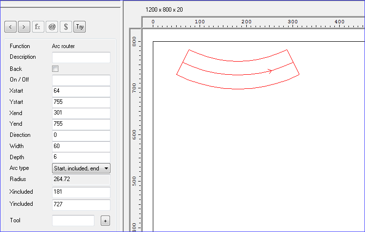
Positioning the included point after the end point produces an arc of direction 2 (>= 180 degrees, anticlockwise) or direction 3 (>= 180 degrees, clockwise).
The radius is read only as it is defined by the position of the included point.
Definition as part of a contour - When creating arcs of this type as part of a contour the first arc is defined start, included, end as normal. All the following arcs then take their start point from the end point of the preceding arc and only the included point and end need be added.
Start, Centre angle
This mode allows arcs to be specified by clicking a start point for the arc, then the centre point for the arc (which defined the radius of the arc) and then dragging out the end point to create the angle range required.
When the start has been defined, a line is drawn to show the positions of the start point and where the centre point will be when the left mouse button is clicked again.
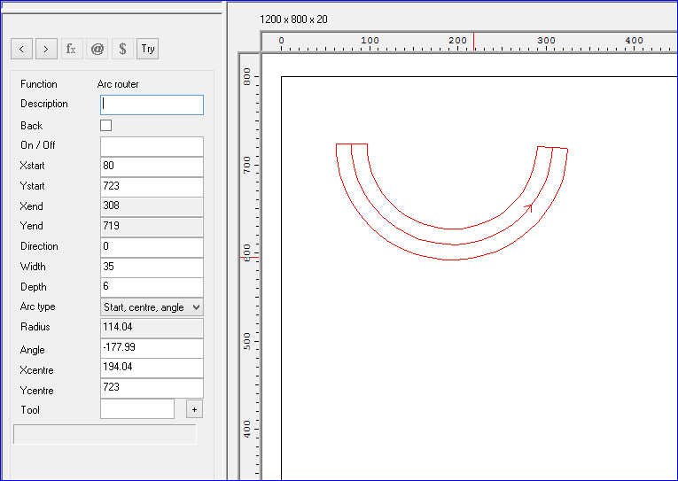
When both the start and centre point have been defined the arc is drawn as the mouse is moved and the end point is defined.
The direction of the arc is determined by the first movement of the mouse cursor after the start point has been defined, clockwise or anti clockwise.
The radius property is read only as this can’t be changed once the start and centre points are defined. There is also a new angle field displayed which allows editing of the angle range of the arc. A negative angle describes an anticlockwise arc, a positive angle a clockwise arc. The end point is also read only as it is defined by changing the angle field.
Definition as part of a contour - When creating arcs of this type as part of a contour the first arc is defined start, centre, angle as normal. All the following arcs are then added by clicking the centre point and end point, this is because the start point will already have been defined as the end point of the preceding arc.
Start, end, radius
With the mode define the arc by first clicking on the start point and then clicking on the end point. Finally move the cursor away from the start-end line to create the radius of the arc. Click to confirm the radius. Move to create the width. Click to finish.
Changing between arc types
It is possible to change between the arc definitions modes once an arc has been defined by choosing a new arc type using the ‘arc type’ combo box in the instructions property view.
This fills in sensible values for any properties that have not been defined in the course of drawing the previous type of arc. For example, if a start, end, radius were defined and this were then changed to a start, included, end arc then the included point would be generated as being then central point of the arc between the start and end points.
If an attempt is made to change an arcs type when the current arc isn’t completely defined then the arc is reset and the arcs drawing will begin anew.
Instruction box
Description - add a description (optional) for the function
Coordinates - Use the Xstart/Ystart and Xend/Yend values to specify the start and end points for the line at the base of the arc.
Direction - use the direction to specify the direction the arc is drawn.
0 - anti-clockwise, less than 180 degrees
1 - clockwise, less than 180 degrees
2 - anti-clockwise, more than 180 degrees
3 - clockwise, more than 180 degrees
Clockwise is defined as though the axis of rotation is pointing into the drawing (right hand rule).
Width - enter the width of the arc
Depth - enter the depth of the arc
Radius - enter the radius of the arc
Tool - use this box to enter the tool number and other information. Click on the [+] button to enter options via a dialog (this is only available for some types of machining centre).
Tool option - Floating on/off for routers - If 1 is entered in this field then EM="1" is written out to the MPR(X) file when transferring to the machining centre. Alternatively EM=1 can be entered directly in the tool field.
![]()