

Convention for the 0,0 point of a Machining drawing
The origin of the drawing is shown by two lines at right angles indicating the x and y directions and the origin.
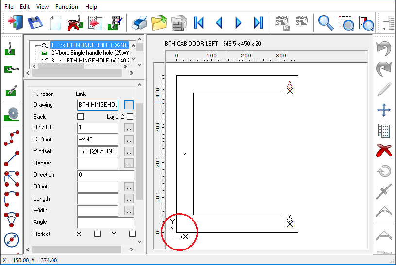
Any of the four points of the drawing can be set as the origin (to match any current convention) but make sure the same origin is used for all drawings.
To choose the origin use the Machining centre parameter: Origin
The options are:-
bottom left
top left
bottom right
top right
The default is bottom left.
Co-ordinates
The co-ordinate system follows the common convention of using y for the vertical component and x for the horizontal component.
Co-ordinates should not be confused with the symbols X Y and Z which are used for the variables associated with a part.
X - part length
Y - part width
Z - part thickness
Note - X indicating the part length is different from x indicating the x co-ordinate.
Also for any formula the following variables are used for the product dimensions.
X - product width
Y - product depth
Z - product height
It is usually clear from the context (part library or product library) which items the X or Y or Z refers to - but take extra care when dealing the products that contain both product and part definitions using a formula.