

Extra instructions for machining tools
Most machining instructions (functions) have a Tool setting; this can be used for extra Tool settings and instructions. These are passed to the Machining centre. These are typically machine specific details for the individual tools and settings. (The specific details depend on each machine and are covered by the manufacturer's instructions). The instructions available and the format to enter are specific to each type of machine, for example, Homag
The operation of the Tool box varies for each Machining type. For example, for the Homag 4.0+ type the Tool Box shows and extra button at the right which gives access to a pop-up dialog showing the specific Homag instructions that can be set for that Function.
This offers an alternative to entering the instructions as text in the Tool Box. (The Machining library type is set by the Machining Library Parameters).
The Tool settings give extra control over the machining centre programming and can avoid later adjustments at the Machining centre.
- Enter each instruction on the Tool box line.
Each instruction starts with a key letter and instructions are separated by a colon.
T=03:Z=10.0
28:Z=3.4:EM=2
If no letter= instruction is specified the item is taken as the tool number information.
$ - Look-up - use the 'Look up' table to add items to the tool box (not available for other fields).You can also use a look-up for the machining centre parameter 'Tool settings for dividing nested patterns'. The look-up is substituted when the run is transferred to the machining centre.
+ button - select this to enter values for pre-defined settings. This button is not available for all transfer modes.
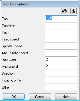
For Homag tool box operations there is an extra dialog which allows you to enter the values directly. Click on the button at the tool box to access the dialog.
Others box - allows you to enter instruction that are not covered by the current range of instructions.
Variables in tool box fields - Variables can be entered into the toolbox fields for instructions. In the machining library they are evaluated using the default variable answers and the evaluated text is displayed in the area below the toolbox.
Lookups substitution in machining drawings - Lookups can be placed in the toolbox field for machining instructions. These can either be in the main drawing or in a link drawing.
Variables specified in toolbox fields are answered in the variable dialog on the Quote / product requirements screen. These answers are used when the machining is created
Variables can be selected in machining library by either pressing the variable button on the machining library screen on by pressing the variable button on the toolbox dialog.
Note: Variables are not allowed in the toolbox dialog when setting the tool setting for nested patterns in the machine centre parameters.
Variables and lookups in Border edge code fields - Variables and lookups can be specified in the border edge code fields.
Lookups in toolbox and edge code fields - Lookups can be specified in the toolbox and edge code fields. Note Variables are only processed if they occur within the lookup entry itself. Variables within nested lookups are not processed.