

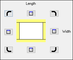
Information box to set method of edging
Use this to specify the sequence and method for applying edging, for example, whether the edging is mitred at a corner or flush.
If this information box is set the program includes the edging diagram data in the information box - and the data can be used elsewhere for drawing the edging diagram (typically on a part label).
Before using the edging diagram for a part the information boxes for the edging for each edge must be set with the appropriate edging codes (where edging is required).
To set the edging methods:-
● Click on the Edging diagram box
The Edging diagram is displayed.
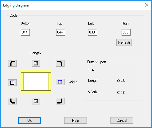
● Enter the edging instructions in the Code boxes
or
● Use the buttons on the diagram to select the method
The edging codes are;-
0 - Flush or Short
1 - Overlapping or Long
2 - Mitred
3 - Rounded Short
4 - Rounded Long
5 - Rounded mitred
blank - None
- Use the 'Refresh' button to update the drawing after a manual change to the edge codes (using this dialog).
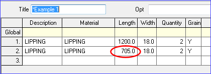
Adjustment of the length of edging pieces based on the edging diagram
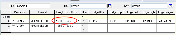
The length of edging pieces is adjusted based on the types of corner set. For example, where all corners are mitred the edging pieces are the same length as the finished sizes.
The part list gives the finished size.
The edging pieces are in the picking list after optimisation.
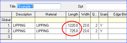
Where for example the corners are specified with an overlap the length of the edging pieces change to account for this.
The length of the edging pieces for the part width (short side) now have a different size to the finished size.
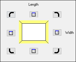
Specifying which part sides are edged first
Clicking the highlighted button below, sets that side of the part to be edged first (shown as a dotted line).
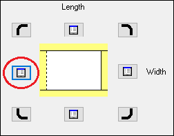
In the example above, the left hand side will be edged first.
The buttons are used to toggle between edged first and not edged first. Clicking the buttons will update the drawing and update the codes at the top of the dialog.
Notes
- The default is 'Rounded long' for the top and bottom edges and 'Rounded short' for the left and right edges.
The main use of this option is to print a diagram of the edging method for each part on a label, e.g. for CADmatic 3, Homag, or Online PC saw types
The order of the codes boxes is: bottom, top, left, right
The data is shown at the part list as a set of codes: e.g. 000 000 011 011
Each code is three digits:-
Digit 1 - edging applied before/after veneer - 0 or 1
Digits 2 3 - edging method at each end of edge
For example:-
Before veneer, Bottom edge flush at both ends - 000
After veneer, Right edge overlapping at both ends - 111
Selecting the edging diagram at Form or Label design - Use the Edges tab to specify whether the edge diagram is drawn, how thick the lines are drawn, and how far in the edge is.
- Edging diagram is not used with the 'Quick edging' method.
- Options 3 to 5 are only available for CADmatic 4
- The edging diagram is updated automatically if the codes are changed at the part list / cutting list, for example, if a code is added or removed.