
Transfer to Homag/Holzma controllers other than CADmatic
The program can be set up to transfer data to other Homag/Holzma saw controllers.
Saw |
Transfer mode |
STG / Videomatic |
1 |
|
This is for the Homag/Holzma saw model numbers 1, 2, 3 (single saws) and 5 (angular) for the STG and Videomatic models.
Transfer to the saw controller for these models is normally by module transfer (mode 1) for which needs a programmer unit and a module (RAM). It is also possible to use transfer modes 2 (Online Label PC) and 11 and 12 (Pattern Exchange) although there is no direct link between the Online PC and these saw controllers. For these models the program automatically generates the cutting instructions (cutting dimensions) needed for the controllers. These can be viewed (if necessary) at the REVIEW RUNS screens.
At the main screen:-
● Select: Machine Interface
● Select the transfer option required
● Select: Transfer to saw
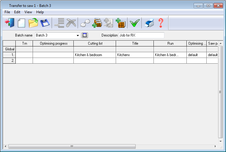
The program displays the batch screen showing the runs to be transferred

● Select OK to continue
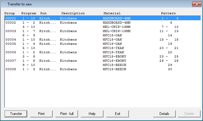
The program shows the details of the transfer.

● Select Transfer to confirm
There are options for printing the transfer details.
Each group consists of a block of cutting instructions.
Details - show the full details of each group
Notes
Saw model 1 (STG16) - Each cutting pattern is represented by a continuous block of cutting dimensions (addresses) in 'programs' of 10. Each address consists of : dimension, cut quantity and function code. For example:-
1362.0 1 0
The first dimension in a set of addresses is typically a drawback dimension. This is calculated by subtracting the falling waste from the board width (ripping) or from the strip length (cross-cutting). If the pattern is an exact fit with zero trims then the drawback produces the first strip (ripping) or part (cross-cutting).
If the saw is rear loading then the first rip dimension is calculated by adding the falling waste to the saw parameter 'distance to cutting line (rip)' .
Only checkerboard strips (identical part dimensions) are considered for crosscutting together and they must obey the saw parameter 'Max crosscut width' (if set) and the clamping rules (if set). If strips are cut together there is a single rip dimension with a quantity of 2 or 3 etc. If checkerboards strips cannot be cut together there is a separate rip dimension for each set with the relevant quantities.
Dimensions take account of the saw parameters: 'min size of last cut' and 'split waste'.
Each pattern may produce more than one program of addresses, in which case the function code for the last address in a program is '2' to indicate that addresses continue in the next program.
The final dimension for a pattern has a function '1'. Otherwise the function code is '0' to indicate a cut.
Addresses to further divide recut blocks are placed in separate programs at the end of the programs for the main pattern.
Saw model 2 (STG19) - The characteristics for this saw model are the same as model 1 with the exception of the function codes:-
- The function code for all drawbacks (head, rip and crosscut) is '3'
- The function code for cuts is '0'
- Function code '1' ends a pattern. This must occupy its own address if the final function code is '3'.
- There is no 'continuation' function code
If rear loading, the function code for the first rip address is '0' not '3'
Saw model 3 (STG16/19 with graphics) - The characteristics for this saw model are the same as model 2 with the exception of the function codes:-
- Function code for drawbacks is '5'
- Function code for drawback with staggered head is '7'
- Function code for drawback with checkerboard head is '8'
- Function codes for ripping are:- '0' or '9' (end of set crosscut together)
- Function code for crosscuts is '0'
Function codes 7 and 8 only apply to the first drawback for the head-cutting operation. The following head cuts (if any) have function code '0'.
The end of the pattern is indicated by function code '1' and this can replace any function code.
Saw model 5 (STG13 Angular) - For this model, addresses are organised into programs of 35 (5 columns of 7). There can only be one program for a pattern and further division of recut blocks is excluded.
The columns are organised as follows:-
1 LS column (rips)
4 QS columns (crosscuts)
On head patterns, head cut dimensions appear in column QS1 and further division of head(s) in QS2 onwards (further division of main begins in the next available QS column). This scheme means that only checkerboard heads are legal (since a staggered head would require its own LS column) and only 3 blocks are allowed in total. This restriction does not apply if saw parameter 'further division of head' is set to 'N'.
The function codes for this model are:-
- Function code '0' for first dimension at start of each cut
- Function code '4' in LS1 indicates that the cut separates strips which are crosscut together.
- Function code '1' for the end of each address block
Some extra rules apply to this saw model and these are explained below:-
Extra drawback (saw parameter)
This affects LS1 on head cut patterns only. When set, the extra drawback value is added to the first dimension for ripping main.
LS1 = main drawback + extra drawback
Crosscut fence rear position (saw parameter)
This applies only on non head cut patterns and affects the first crosscut dimension in each QS column.
QSn (1) = Crosscut fence rear position - board length + falling waste.
The saw parameters 'crosscut fence rear position' and 'extra drawback' are mutually exclusive.
Distance to cutting line: rip, crosscut (saw parameter)
When set, these values are added to the first LS1 or QS dimension