

Default settings for each drawing
These settings apply to all new drawings. At the machining screen:-
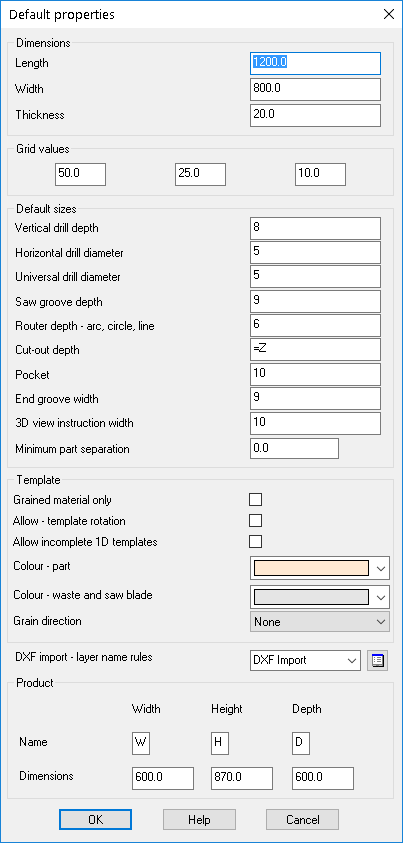
● Select: File - Default properties
The Default properties dialog is displayed.
● Check or set values as necessary.
These values apply for ALL new drawings.
Properties
Grid values - Enter values for grid spacing in the grid boxes
Default sizes - default sizes for Machining functions
Vertical drill depth
Horizontal drill diameter
Universal drill diameter
Saw groove depth
Router depth (arc, circle, line)
Cut out depth
Pocket depth
End groove width
3D view instruction width - This allows a width to be specified for instructions that don't specify a width
Minimum part separation
Parameters for Nesting templates
When working with templates for Nesting the following three parameters are used.
Minimum part separation
Grained material only
Allow - template rotation
Router diameter - specifies the gap between the parts for the current template drawing. This must match the router diameter specified in the optimising parameters when the template is used.
Grained material only - if a pattern does not have a grained material the template is not used when creating nested patterns. Set this parameter OFF to force the use of grain match templates for non-grained parts.
Allow template rotation - set whether the template can be placed on a pattern in the rotated orientation.
Colour - part - specifies the colour that is used to show parts on the nesting template drawing.
Colour - waste and saw blade - specifies the colour that is used to show waste parts on the nesting template drawing.
Allow incomplete 1D templates - When this option is set a one dimensional template no longer needs parts assigned to every position in the template and the nesting template calculations automatically adjust the part positions accordingly
Grain direction – Specifies the grain direction for the template. If the grain direction is ‘None’ there is no specific grain direction and all parts in a template must have the same grain. If the grain direction is ‘Lengthways’, parts with Y or N grain have the same orientation as the template and parts with X grain are rotated by 90 degrees. If the grain direction is ‘Widthways, parts with X grain have the same orientation as the template and parts with Y or N grain are rotated by 90 degrees.
Dxf import - layer name rules
This option is available if the system is set up to use DXF based parts which are user defined; Machining centre parameter: Import DXF format set to 'Layered - user defined'
 Use the list box to select a file for the 'DXF import layer name rules
'
Use the list box to select a file for the 'DXF import layer name rules
'
Product dimensions
The product dimensions section is used to specify which characters are used for the product dimensions in a formula in the machining library and what the default product dimensions will be used for displaying machining library drawings if the values are referenced in formula.
The list of legal characters is a single alphabetic character from A-Z but not X, Y or Z or T (as it is used for thickness for material) or F (use for fractional values).
You only need to specify dimension names if they are used within any drawing, so if only the product depth needs to be referenced in machining drawings, the dimension names for product width and height can be left blank.
Notes
- Some parameters are not used (grayed out) if the drawing is a template.
- 'Router default depth' applies to circle, groove and arc routers.
![]()