

Part list option (View menu) to show the part drawing
Part drawings can be shown at the part list. At the part list screen:-
● Move to the 'Code' column
(The drawing can only be switched on/off when the cursor is located at the code column)
● Select: View - Drawing
 Check / Uncheck the menu option to show or hide the part
drawing.
Check / Uncheck the menu option to show or hide the part
drawing.
or
![]() Select
the toolbar symbol (this toggles the drawing on / off)
Select
the toolbar symbol (this toggles the drawing on / off)
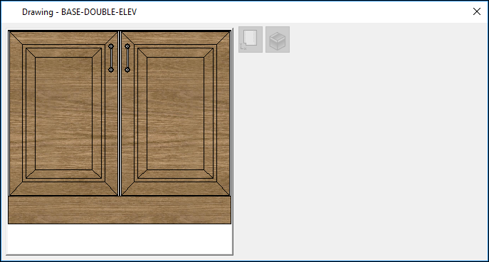
● Click on or move to a part record to show the drawing. The drawing is shown in a pop up dialog.
The drawing shown and options available depend on the 'Drawing source' used for the part list (File - Properties).
The  and
and
 buttons are used to switch between 2D and 3D versions of the machining
library drawing.
buttons are used to switch between 2D and 3D versions of the machining
library drawing.
Inside the 3D drawing the mouse is used in the following ways:
Left click- rotate
Right click - pan
Mouse Wheel - zoom
Double click middle button - reset drawing orientation
Drawing source - Part library / Machining library
The dialog also shows any variables for the part (and answers for the variables). These values can be edited.
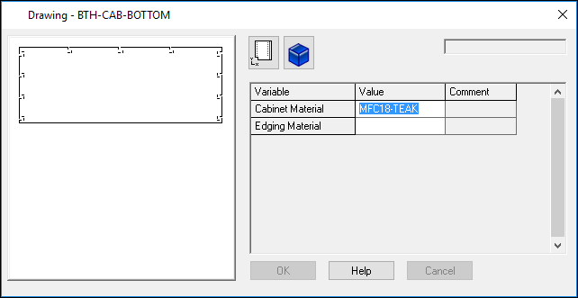
- OK and Cancel are greyed out unless the variables are changed
- Double click the drawing to move to the machining library
- Close the Window or use the View menu to turn off the part drawing
The variables shown are those used in the part library and/or machining library. For example, @CARCASEMATERIAL@, @HINGEWIDTH@ .... Typically the variables are defined in the Variables table but there may also be other variables used in the part library or machining library which are not set in the variables table.
Drawing source - MPR(X) files
The dialog also shows any variables for the part (and answers for the variables). These values can be edited.
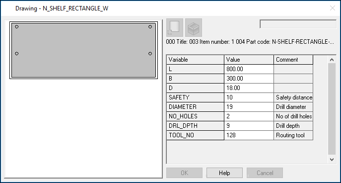
- Double click on the drawing to move to the WoodWop MPR(X) editor.
The variables are defined in the MPR(X) file and different parts may use different variables but typically many of the variables are common across parts.
When the part list drawing source is MPR(X) the drawing dialog is always ON. This is because the length/width columns are disabled and the dimensions used are those from the 'L,B,D' variables in the MPR(X) file.
Comment lines
The text shown above the variables table are the comment line from the '<101' section of the MPR file. Ellipsis indicates that there is more text than shown. Place the mouse over the text to see the full text in a tooltip.
Drawing source - DXF files
The DXF drawing is shown. There are no variable items.
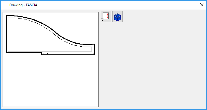
The drawing cannot be edited at the part list.
The
and
buttons are used to switch between 2D and 3D versions of the DXF drawing.
Inside the 3D drawing the mouse is used in the following ways:
Left click- rotate
Right click - pan
Mouse Wheel - zoom
Double click middle button - reset drawing orientation
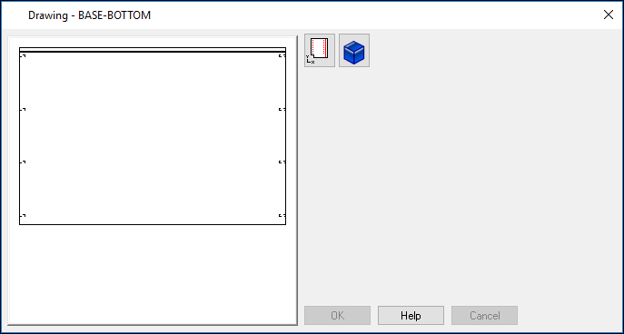
Drawing source - Drawing library
The drawing from the Drawing library is shown. There are no variable items.
The drawing cannot be edited at the part list.
Notes
- At the Board list screen the material picture is shown in a pop-up window.
- Ctrl Tab - move between the part list grid and drawing dialog
- Variables are set up in the Variables table
- Where the part list source is MPR(X) the drawing window also includes the option to edit the MPR(X) variables
- For items in the machining library the variables come from the part library or from the associated drawing in the machining library
- The range dialog only applies to machining library variables.
- Double click the drawing to move to the machining library
Part list information boxes
If any information boxes are set for variables these are locked and the values can only be changed in the drawing dialog. Any changes are automatically applied to the information boxes. (See topic: Variable - Information box)
Import parts
Variables answers can be imported with part lists via the Import parts option (user defined)
When importing parts (user defined format) the import process can bring to variable answers for machining library drawings. Variable answers can come from multiple sources so the order of variable processing is as follows:
- Information box variables specified in fixed field positions
- Name variable specified in fixed field positions (with the Variable 1 to Variable 25 parameters)
- Answers specified as @VAR1@,ANS
Part list - editing variables
Variables can be edited in either the drawing dialog or the variable information boxes but not at the same time.
If the drawing dialog is switched on the variables can be edited in the drawing dialog and the variable information boxes are greyed out. Any changes made in the drawing dialog are reflected in the relevant variable information boxes when OK is selected.
If the drawing dialog is switched off the variable information boxes are enabled. Any changes made to the variable answers are shown in the drawing dialog when it is next switched on.
The software has been modified to only show the first 300 variables from any part MPR file. It is very important that any variables that are involved in the size of the part or the border / safety geometry are specified within the first 300 variables.
Drawing dialog switch on/off
When the drawing dialog is closed via the Windows close button ('x') the drawing dialog is switched off and does not re-appear until the drawing dialog is switched back on via either the drawing menu option (View menu) or via the new Drawing toolbar button (to the left of the Optimise button).
The drawing dialog only appears when the current grid line contains a code (part or board) so, for example. the drawing dialog is not shown for new part list lines.
(The drawing dialog is always on when the drawing source is set to MPR(X)).
Notes
- The drawing dialog is also available for boards at the board list.
![]()