

How to create shaped parts
Shaped parts are defined by drawing contours that define the shape of part. This is done at the Machining library or via the MPR(X) file using Homag WoodWop.
At the Machining library use the Border function to define the shape of the part.
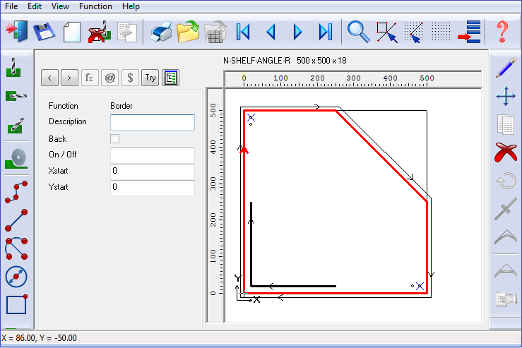
If a Safety border is required this is added as a contour surrounding the shaped part and is set as a safety border by checking the Safety box in the contour function.
For an MPR(X) file two closed contours are required (similar to the above) to define the shape of the part and the safety border. Check the 'Nesting contour' option for the first contour and the 'Nesting safety distance' option for the second contour.
If a safety border is not defined the Nesting parameter 'Nesting safety distance' is used instead to calculate a safety border at a uniform offset around the contour of the shape.
A set of Information box parameters are available for Nesting to control features of each part, for example, Step angle, Priority, Mirrored.
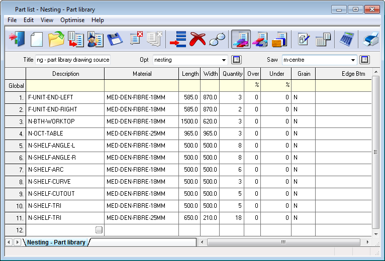
Information boxes are set from the main screen (Parameters - Information boxes). Once the Part list is set up the program creates a list of cut sizes (cutting list).
![]()