

How to work with parts with DXF based drawings and DXF based patterns
DXF is a common format for part and pattern drawings. To use this format the Optimising program has to import or read part and pattern drawings in the R12 DXF format and after optimisation output patterns and machining instructions to a file in a defined DXF format.
- For import use the 'DXF import - layer name rules' to describe the DXF format (Main screen - Parameters - 'DXF import - layer name rules' )
- For transfer to a machining centre the program uses a predefined DXF format (Main screen - Machine Interface - 2D DXF Nested Layered)
The DXF format is essentially a drawing format describing the geometry of a drawing. The information for machining (drilling, routing, etc.) is stored separately in different 'Layers'. Typically there is a layer for drilling, a layer for borders and so on.
Layering - Layering is a mechanism in the DXF format which separates the drawing elements into series of layers or overlays. Each layer can be identified and its contents separated from the other layers. The layer names and the layer contents can be chosen by the user so that is a very flexible way of structuring the information in a DXF file. The different layer options available are just the different conventions that manufactures and users have set up for naming layers and deciding what information is in each layer.
These layers are typically named and defined differently by each user depending the type and quantity of information they use. Within a DXF file there can also be many other 'Layers' containing information on the drawing or the project which are not used by the Optimising program.
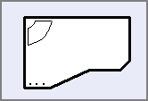
Below is a simple example of layers in a DXF file for storing machining information.
DRILL-5MM
DRIL-8MM
GR-ROUT
Working with DXF based parts
Where parts are based on DXF files there are a number of ways of working with these.
- Use the DXF parts directly in part lists
- Import parts into the Part library
- Import parts into the Machining library
Once the parts are in a part list they can be optimised and transferred to a machining centre in the usual way.
For details of each method see the topic: Working with DXF based parts
Notes
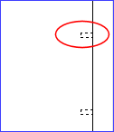
- When horizontal drilling instructions are imported from a DXF file they may be represented in the DXF file as 3 separate lines or as the DXF instruction 'Polyline' or as the DXF instruction 'LwPolyline'. The import process recognises these different DXF instructions and automatically converts them into the correct Machining library function.
(An example of a horizontal drilling instruction is highlighted below.)
- The depths of geometry in DXF files can be used during the import for the depths of the instructions. See DXF Import - layer names with field values for more details
![]()