

How to use DXF based parts
Where parts are based on DXF files there are a number of ways of working.
- Use DXF parts directly in part lists
- Import DXF parts into the Part library
- Import DXF parts into the Machining library
Once the parts are in a part list they can be optimised and transferred to a machining centre in the usual way.
Use DXF parts directly in part lists
- Copy the R12 DXF files to the directory set by the system parameter: Path for Import data
- Move to a part list
- Select: File - Properties
- Set the drawing source for the part list as: DXF files (this can be different for each part list)
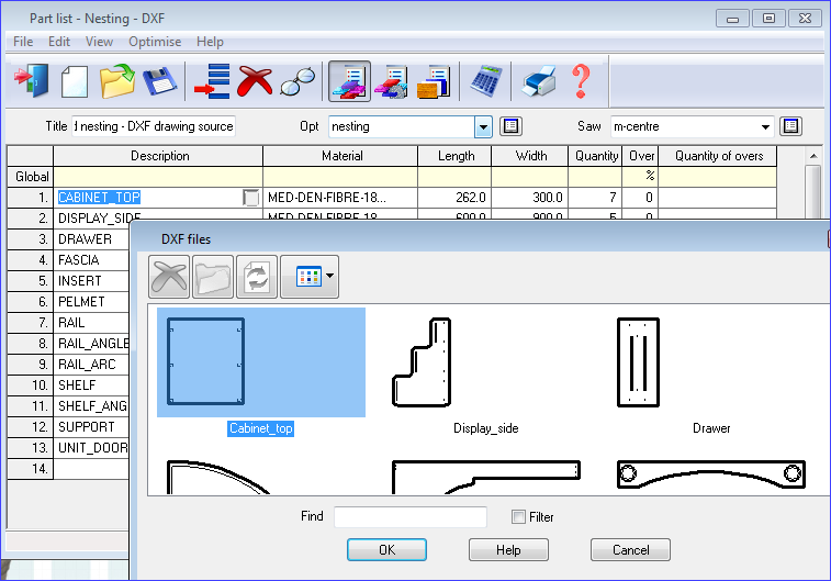
At the part list the DXF parts are now available from the selection dialog.
Import DXF parts to the Part library
- Copy the R12 DXF files to the directory set by the system parameter: Path for Import data
- Move to the Part library
- Select: Edit - Import DXF drawings
- Select the required DXF drawing
The item is now stored in the Part library and there is a drawing in the Machining library.
- Move to a part list
- Select: File - Properties
- Set the drawing source for the part list as: Part library (this can be different for each part list)
At the part list the DXF parts in the Part library are now available from the selection dialog.
Import DXF parts to the Machining library
- Copy the R12 format DXF files to the directory set by the system parameter: Path for Import data
- Move to the Machining library
- Select: File - Merge DXF
- Choose the directory with the DXF files
- Select the required DXF drawing
The item is now stored in the Machining library.
- Move to a part list
- Select: File - Properties
- Set the drawing source for the part list as: Machining library (this can be different for each part list)
At the part list the DXF parts in the Machining library are now available from the selection dialog.
Machining instructions
For parts processed at a Machining centre the DXF file also contains machining instructions. This format can be different for each user. Use the 'DXF import - layer name rules' to describe this format.
Notes
- Shaped DXF parts are only used with the Nesting optimisers
- The default drawing source for all parts lists can be set via: Part list parameters
- All DXF files to be used must be in R12 format for the program to use them
DXF import - Rectangular borders
During a DXF import - if a rectangular border is imported and it is made of 4 routs (so it starts in one of the corner) the border is replaced with a 5 rout border that starts halfway along the top edge and goes either clockwise or anti-clockwise depending on the system parameter 'Generate anti-clockwise borders'.
DXF import - 2 arc contour/borders
A 2 arc rout border is imported as 2 arcs. The 2 arc rout contour is set to the direction specified in the DXF layer name rules.
DXF import - small contours/border routs
Small lines part of a polyline contour are not removed during the import process. This allows the contour to be completely closed and set clockwise or anti-clockwise according to parameter settings.
![]()