

Settings to describe the machining information for DXF files
Only for Machining interface
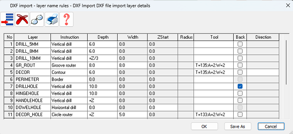
Use these parameters to describe the layer structure of an R12 DXF file for machining information. This information is required if DXF files are used as a source for parts, in the part list, part library or machining library. At the main menu:-
● Select: Parameters - DXF import - layer name rules
The program displays a dialog.
● Enter a layer name
or
 Select a layer name
from a list
Select a layer name
from a list
(Click on the Layer column to pop up the select button)
Initially the program prompts to select the folder containing the DXF files. Select the required folder. This selection is retained for future sessions.
If no names are available or more layer names are required a list of layer names can be prepared by scanning existing DXF files - for details see: Scan - DXF.
For each layer name enter the layer details for each column.
Instruction
Enter the type of instruction stored in the layer name. Some examples of available types are:-
Vertical drill
Horizontal drill
Saw groove
Circle router
Groove router
Arc router
End groove
Contour
Text
Border
Safety Border
Free form pocket
In the next columns enter the information for Depth, Width, Zstart, Radius and Tool where it applies for each instruction type. This is information that is NOT in the DXF layer but needs to be set for Machining.
The information required for each machining type is.
Vertical drill: Depth, Tool
Horizontal drill: ZStart, Tool
Saw groove: Width, Depth, Tool
Circle router: Depth, Width, Tool
Groove router: Width, Depth, Tool
Arc router: Width, Depth, Tool
End groove; Width, Tool
Contour: Depth
Text:
Border:
Pocket: Depth, ZStart, Radius, Tool
At the Tool column click on the button to pop up the tool dialog to enter
the Tool information.
Back
The column 'Back' is for specifying that for the current layer name, the instruction will be imported onto the back of the drawing. The back check box is not available for the following instructions:
Horizontal drilling
End grooves
Border
Safety
Text
Direction of imported contours / free form pockets
The column 'Direction' is for specifying the direction of contours, pockets and free form pockets. This is available where the instruction is a contour, pocket or a free form pocket. Enter one of the following values:-
Blank - contour/pocket direction depends on the way it was drawn in the original DXF drawing)
CW - contour/pocket is drawn
in the machining library in a clockwise direction ![]()
CCW - contour/pocket is drawn
in the machining library in a counter clockwise direction ![]()
 Use the combo box to select an option
DXF Import - instruction depths relative to the material thickness
During the DXF import the depth of each machining instruction can be set relative to the material thickness.
The Depth column value can be either a fixed value (e.g. 9 or 5.75) or it can be a formula referencing the Z (material thickness).
=Z/2 means half the material thickness
=Z-3.5 means 3.5 mm less than the material thickness.
Only the constant Z can be used (no variables or formulae names can be entered here
For the horizontal drilling the depth value adjusts the ZStart field, for Pocket the Radius is adjusted. For the following instructions the depth is adjusted:
Vertical drill
Saw groove
Circle rout
Groove rout
Arc rout
Contour
Free form pocket
For Contour and Free form pocket - the depth applies to the contour instructions and all the routs.
DXF Import - geometry depths from file
The depths of geometry in DXF files can be used during the import for the depths of the instructions.
In order to use this, the depth column in the DXF import layer name rules parameter needs to be set to 3DDXF.
See the help topic: DXF Import - layer names with field values
Extract field data from the layer name
Data can also be extracted from layer names. For example, the following layer name has data incorporated in to the name.
ML_DEP$12_5$_WID$3_5$
See the help topic: DXF Import - layer names with field values
Other options
Save As - Save the existing list to a new filename
OK - accept changes and exit
Print - print a copy of the list of parameters
Help - information about this dialog
Cancel - abandon changes and exit
Notes
- Only R12 format DXF files can be used by the program
- Layer name maximum length is 100 characters
- Up to 100 parameters lines allowed
- Machining centre parameter: Import - DXF format must be set to ' Layered - user defined'
- Only layer names that are used for geometry are shown in the selection dialog
- When transferring a machining drawing in 2D DXF nested layered DXF format any fixed pockets (not free form pockets) appear on a layer starting with the text 'POCKET'
The display of DXF drawings in the selection dialog in DXF layer rules has been changed so that all lines, arcs, polylines are now shown independent of their layer name.
- All lines, arcs, polylines are now shown independent of their layer name.
- Some characters are not allowed within layer names (e.g. < > / \ " : ? * | , ;). These are automatically replaced by the underscore character '_ '.
- Circles. A circle in a DXF drawing can be imported as a contour, safety, or free form pocket (with User defined layers). As with a border based on a circle the resulting contour consists of two arcs.
![]()