

System parameter to set how borders are generated
This specifies the direction (clockwise or anti-clockwise) in which borders are generated by the program. The default is 'anti-clockwise',
 Check
the box for anti-clockwise borders
Check
the box for anti-clockwise borders
The border direction is the direction in which the border is machined. Borders are created in the following situations.
- At the machining library
- Import DXF file to machining library or part list
- Border automatically generated if a part does not have a border
Wherever the program imports or creates a border the border direction is set to match this parameter value.
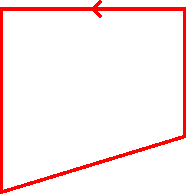
Border direction display
In the machining library the direction and tool path are displayed on the middle rout of the border. The direction is indicated by an arrow going clockwise or anti-clockwise along the routs. The tool path is indicated for RK=1 (left) or RK=2( right), by any arrow pointing into or out of the border.
Notes
- The direction of a contour or border can be changed via the change direction facility. This is accessed by selecting a rout on a contour / border and then selecting Change direction from either the right click popup menu or the edit menu.
- When a border is partially created and right click popup menu is used to close the border the parameter is used to define whether the border finishes in a clockwise or anti-clockwise direction.
- When a contour is changed to a border the direction is changed to match the system parameter setting.
|
|