

Saw transfer parameters to set values for establishing a link to a machine
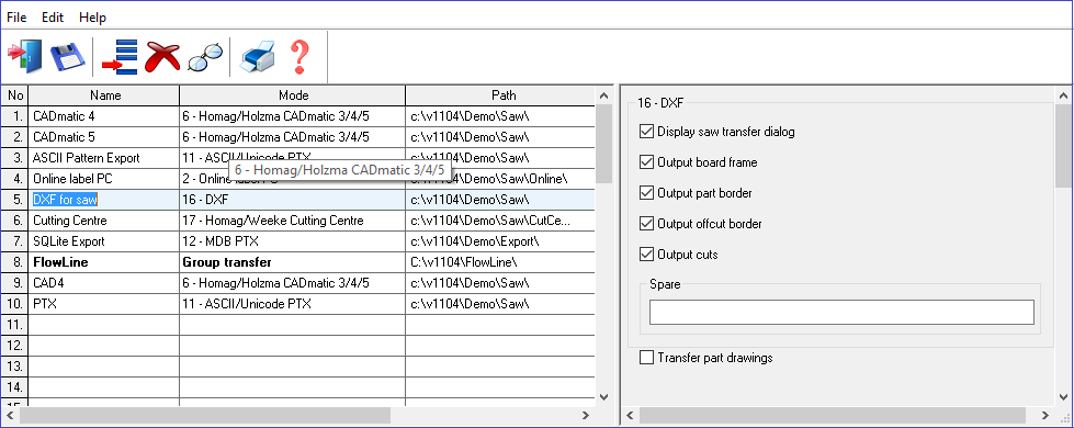
For saw transfer to DXF there are a series of options for the format of the output files. These are shown at the Right of the screen.
 check a box to include an option
Display saw transfer dialog
Output board frame
Output part border
Output offcut border
Output cuts
Display saw transfer dialog
Sets whether this information is shown during transfer (it is usually not needed except for some of the older saw transfer methods). See the Saw transfer parameter: Display saw transfer dialog.
DXF settings
A DXF file consists of a series of different (user defined) layers. These settings determine whether the layer is output to the file or not. A DXF file describes the Geometry of a drawing and for saw transfer it may not be necessary to include the perimeters in the output files as they do not represent a cutting operation. The layer names are fixed.
Output board frame - the perimeter of the board/pattern (Layer name: 'BOARD')
Output part border - the perimeter of the part (Layer name: 'PART')
Output offcut border - the perimeter of the offcut (Layer name: 'OFFCUT')
Output cuts - the cut instructions (Layer name: 'CUT')
BOARD, PART and OFFCUT items are POLYLINE entities
CUT items are LINE entities.
Items in each layer are grouped together and sorted so that the strips are processed bottom to top, left to right.
...
8
BOARD
10
0.00
20
0.00
30
0.00
0
VERTEX
8
BOARD
10
0.00
20
1220.00
30
0.00
0
VERTEX
8
BOARD
10
2440.00
20
1220.00
30
0.00
0
VERTEX
8
BOARD
10
2440.00
20
0.00
30
0.00
0
...
Example of DXF file
The 'Spare' parameter box is currently not required
Notes
- The DXF transfer mode is compatible with all saw models
- The DXF transfer is also available with the 'Stand alone' options
![]()