

3D view of machining library drawing
A 3D view is available of the current drawing via the 3D view button on the standard toolbar in the machining library:
![]()
Once in the 3D view the 2D drawing can be returned to by pressing the 2D view button next to the 3D button on the standard toolbar:
![]()
Examples:
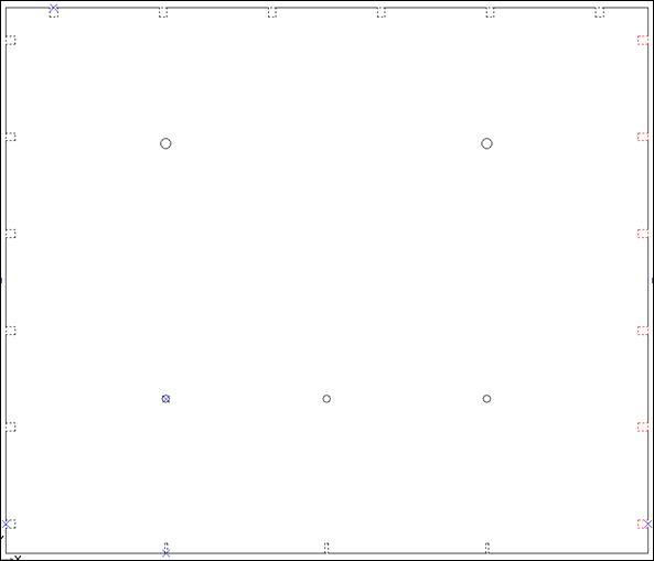
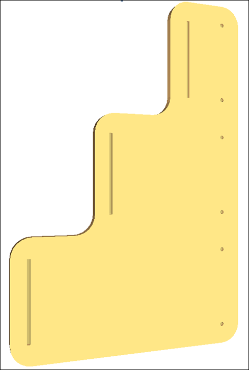
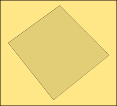
BTH-CAB-BACK in the standard 2D view
In the 3D view the 3D representation of the part is first presented as a view from above
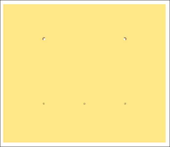
The view can be manipulated by clicking on the screen using the left mouse button and dragging to rotate the part around the vertical or horizontal axis. The part can also be zoomed in and out using the mouse wheel. If the right mouse button is pressed and held then the image can be panned around to allow viewing of a specific piece of the part.
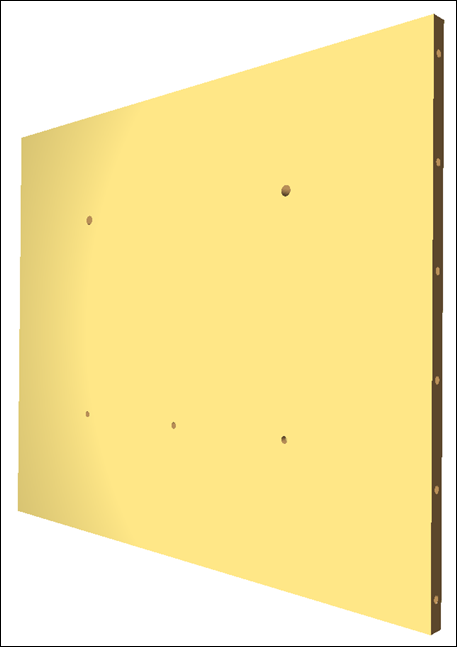
Choosing the 3D view for a drawing which includes a border will use the border to define the shape of the part.
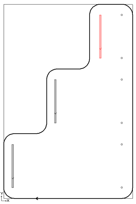
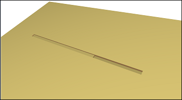
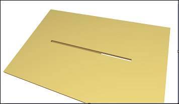
M-DISPLAY-SIDE
3D view of M-DISPLAY-SIDE
Pressing the central mouse button or mouse wheel resets the view to its original orientation. The view can also be reset using the reset view button on the standard toolbar.

Pressing the down arrow to the right of the reset button displays a drop down menu which allows several pre-set views of the part to be chosen.
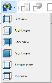
These views can also be chosen from the view menu.
Notes:
The default properties dialog contains a new 3D view instruction width setting which allows a width to be specified so instructions that don't specify a width can be displayed.
Contour rendering
There are three ways that contours can be represented in 3D drawings.
- A contour containing some instructions that don’t cut all the way through the part, these instructions are rendered as expected. Taking into account the path specified in the contours pass.
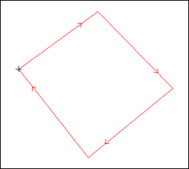
Closed contour, instructions don’t cut all the way through the part
Becomes:
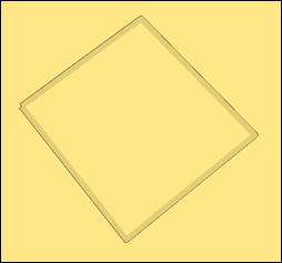
Contour cut into the part
- Closed contours where every instruction cuts all the way through the part.
With these contours the instructions are cut out from the part and also the space contained within the contour. In this case the pass of the contour is considered when rendering the 3D view, so the ‘outside edge’ of the contour will determine the shape
Closed contour with all instructions cutting all the way through the part
Becomes:
.PNG)
Shape contained by contour is cut out of the part
- Closed contour marked as a pocket, in this case the depth of the pocket is taken from the depth specified in the contour. The path however is determined from
the winding of the contour, so the cut is always made inside the centre line of the contours instructions. A clockwise winding will have a path of 2 and an anti-clockwise one will have a pass of 1.
Contour Pocket
Becomes:
Contour pocket rendered in 3D
Contour passes
A single contour is added to the 3D scene for each pass it has specified. Each pass is added for the instructions specified in that pass.
This example shows a three instruction contour with two passes. The first pass covers the entire contour at a depth of 5. The second pass includes just the third instruction at a depth of 10
The depth of each added pass is the depth of the instructions combined with the depth specified in the pass. The image below shows the previous example but with a depth of 10 specified for each instruction. This gives the first pass a new depth of 15 and the second pass a new depth of 20.
The same contour but with instructions with a depth of 10 specified in the instructions.