

Methods to connect parts together in the 3D builder.
When two connectors have been joined together they are referred to as a connection.
Once the first part has been positioned the product can continue to be built by connecting parts to it.
The simplest way to do this is by adding a connection between instructions.
1) First a part has to be chosen to be added by clicking on one of the pictures on the list on the right hand side of the screen.
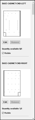
The parts in the list show how many of each part are available. If there is more than one part in the product then the extra instances of the part can be accessed by clicking again on the picture once previous instances have been added to the product.
The quantity available of each part is printed below the edit and remove buttons. In the example above ‘BASE-CABINET-END-LEFT‘ is listed as having 0/1 available because the single instance of that part has already been used in the product as the first part.
In addition there is a button to remove a part that has already been added to the product.
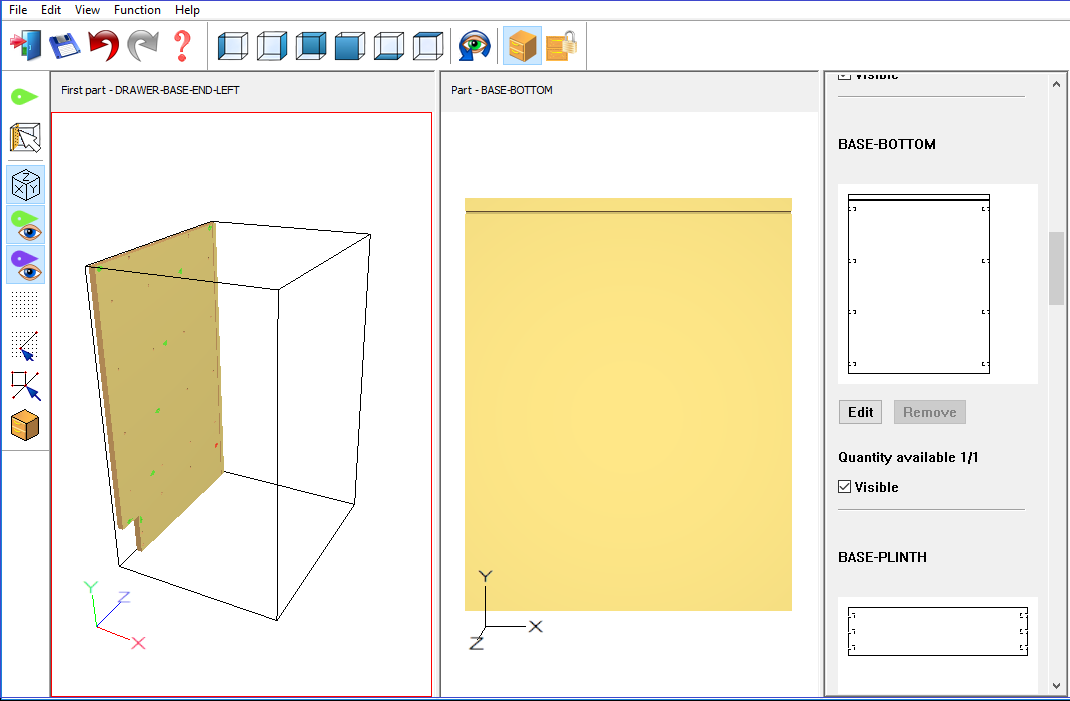
Once a part has been selected to add it will appear in the central ‘part’ view. Once there, it can be rotated or moved about using the left or right mouse buttons respectively. In the same way as in the 3D view in the machine library.
2) Right click on a parts instruction to add a connection to another part.
A connection can be added by right clicking on a drill instruction and choosing ‘Add connection’ from the resulting menu:
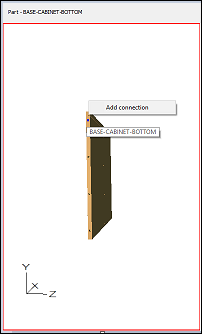
When the mouse cursor is over an instruction the instruction will be highlighted in blue to make it clear what is being interacted with.
3) Choosing the other instruction to connect with
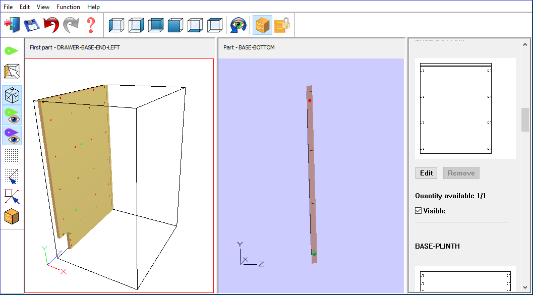
Once an instruction has been chosen the view will be greyed (the middle view in the example above) and the potential instructions that can be connected with will be highlighted in red in the other view (the left hand side view in the example above).
As the mouse is moved over the part, instructions are highlighted blue. Click on an instruction to join the parts.
4) Connected parts
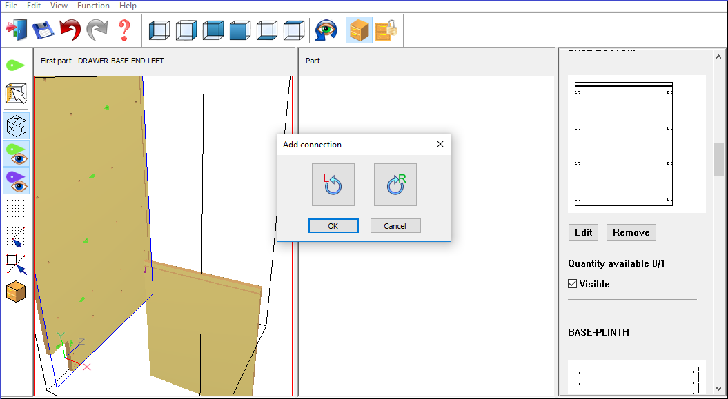
Once the second instruction has been clicked upon the connected parts are shown in the left hand side product view. The ‘add connection’ toolbar is also displayed in middle of the screen.
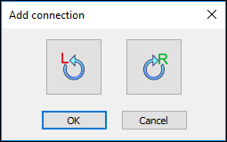
The ‘Add connection’ toolbar allows the connection between parts to be confirmed or cancelled. It also allows the parts to be rotated against each other using the rotation buttons.
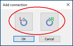
In the example above the parts are not initially lined up correctly, they can be corrected by pressing the right rotation button once. The connection can then be confirmed by pressing the OK button:
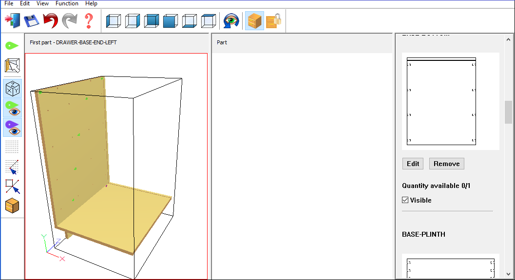
The confirmed connection, the part has now been added to the product and is shown in the left hand side product view.
![]()