

How to work with simplified MPR based parts
To use this option the following system parameters must be checked:
Nested pattern and part drawing view must be set to standard view (on the Nesting tab).
Source MPR files - flat (non-parametric)
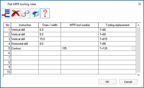
The first column is used to specify an instruction type. The next two columns can be used to either specify a diameter / width or tooling specified in the MPR file.
The final column is what the tooling will be inside the software.
e.g. So in the example screen shot above:
Vertical drilling in the MPR files with a diameter of 6.0mm will end up with a tooling of T=66
Vertical drilling in the MPR files with a diameter of 8.0mm will end up with a tooling of T=68
Vertical drilling in the MPR files with a diameter of 15mm will end up with a tooling of T=615
Horizontal drilling in the MPR files with a diameter of 8.0mm will end up with a tooling of T=88
Contours in the MPR files that have the MPR tool number set to 105 will end up with a tooling of T=128 in the software.