

Settings for the operation of drawings
These properties can be adjusted for each drawing although often the same properties are suitable for a range of drawings. At any drawing:-
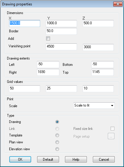
● Select: File - Drawing Properties
The program prompts with a dialog to enter the values for the properties.
Work through the various values and adjust as required. It is worth experimenting with some settings to get a feel for the different effects.
Dimensions (X Y Z) - Enter the width, height and depth for the guide box. The units are the units you are working for in the drawing. For example if you are working in millimetres you can use millimetres or if you are working in inches use inches. It is best to keep the same units for all drawings. Note that when you set the size of the guide box this automatically sets the size of the drawing area.
Border - this is the size border between the guide box lines and the edge of the drawing area. It is usually helpful to have a small border as this makes it easier to view the guide box.
Add to drawing - the guide box is usually temporary and can be switched off - but you can check this box so that the guide box that is created is a permanent drawing object.
Vanishing point - set the X and Y co-ordinates of the vanishing point - this can be a point outside the visible drawing area. The vanishing point is the imaginary point at which the perspective lines converge so if you move the vanishing point the perspective changes. The drawings use a single vanishing point which is fixed for the whole drawing. This gives the three-dimensional effect of looking at the drawing from a fixed position.
Note - for a new drawing can also change the vanishing point using the cursor keys, for example, pressing [CURSOR UP] moves the vanishing point up the horizon and pressing [CURSOR RIGHT] moves the vanishing point to the right. If you are not sure what to do just try a few experiments with moving the vanishing point and you will quickly see how to get the perspective you want.
Drawing extent - These values are for the extent of the drawing and the border. If you are working in millimetres then the following drawing extent represents a rectangle of 1000mm x 800mm.
LEFT 0
RIGHT 1000
BOTTOM 0
TOP 800
Note that the drawing is always automatically sized to fit the screen area or the printed area available. The printed area depends on the page size and orientation set for you printer.
Grid values - these values to set are for the Grid spacing at different resolutions. Use the same units as the drawing extent. A set of values of
50
25
10
Represents a grid spacing of 50mm, 25mm, and 10mm if you are using millimetres as units.
Print - Set the scale for printing. The combo box offers several common choices such as 'Scale to fit' or 1:1. The default value is 'Scale to fit'.
You can enter any scale such as 140:750 provided that it is in the format 'xxxxx:xxxxxx'.
If the measurement is in millimetres than a scale of 1:100 means that one 1mm on the paper represents 100 drawing units. If the measurement mode is inches then a scale of 1:100 means that 1 inch on the paper represents 100 drawing units.
Display scale on drawing - Add a text object to the drawing and enter '<SCALE>' in the text field.
Type - Select the type of drawing
Drawing
Link
Template
Plan view
Elevation view
For a Link type also specify whether the link is a fixed size
For a Template there is an extra dialog for setting up the page
Page setup - for type template. Click on the button to select the Page Setup dialog. Use this to set the page size and orientation for a drawing template.
Select the paper size from the Combo box. The other options are:
Portrait
Landscape
The page setup dialog appears automatically when creating a new template.
Notes
- Page orientation affects the drawing extents.
- The page setup can also be changed on printing at the 'Print dialog'.