

Diagram or picture for a part
At the part library screen a drawing can be linked to each part.
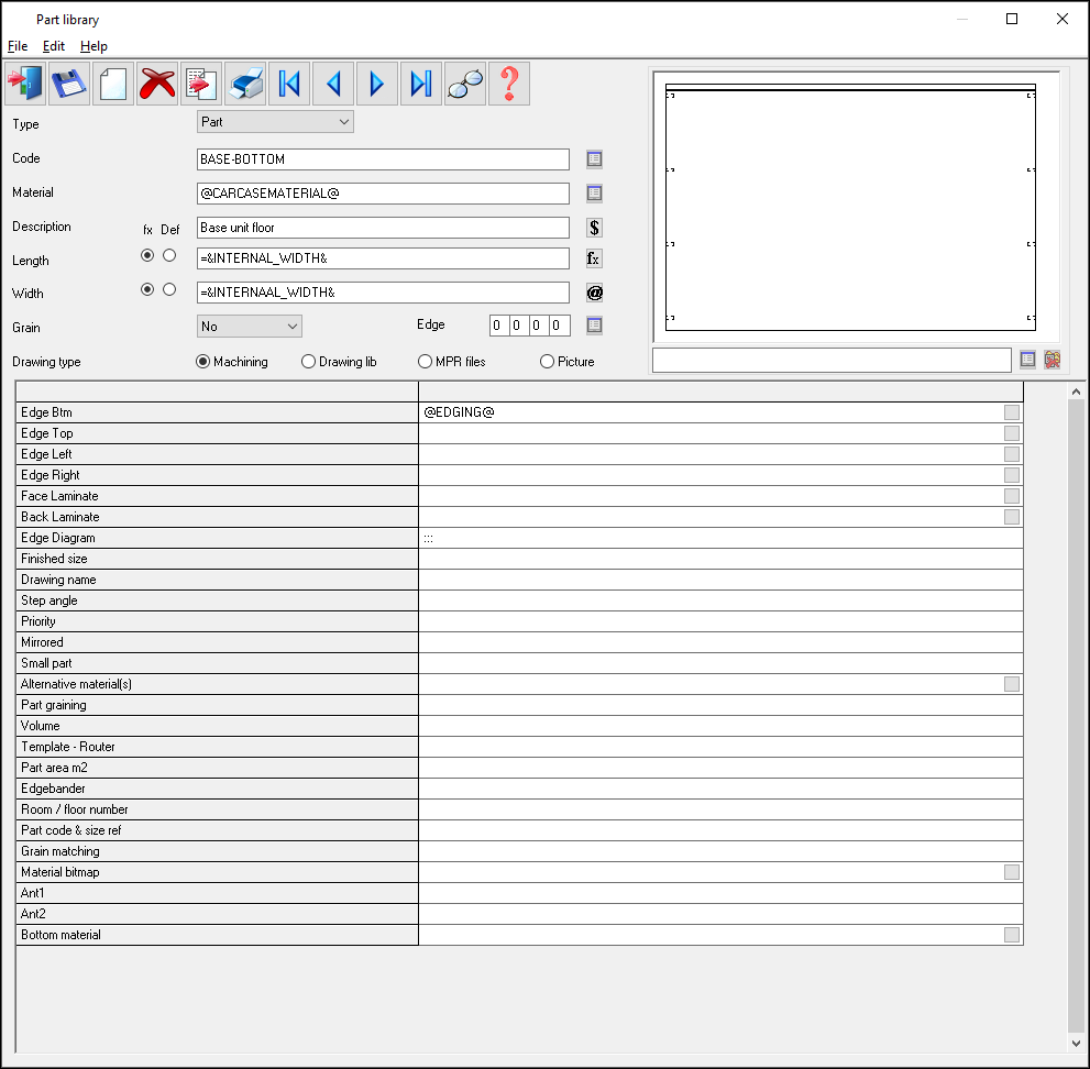
The default drawing name is the same as the part code, for example, BASE-CAB-01
The drawing can be selected from one of several different sources:-
- Machining library
- MPR(X) file
- Drawing library
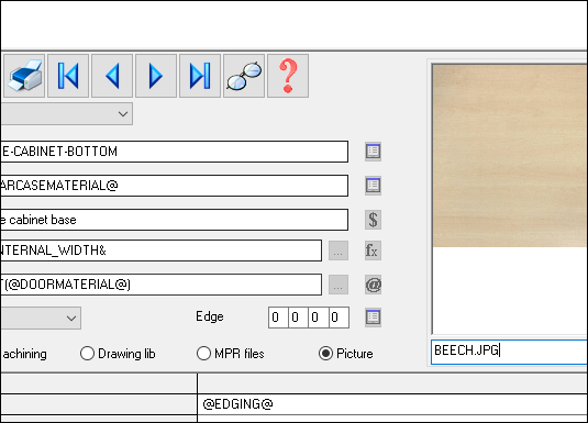
- Picture (external graphics file BMP, WMF, EMF, JPG)
● Select a radio button from the 'Drawing type' line to set the drawing type
The drawing can also be selected with a different name by entering the file name in the box, for example:-
Standardpart-01.bmp
![]() - browse machining library
- browse machining library
![]() - browse MPR(X) files
- browse MPR(X) files
![]() - remove part drawing name
- remove part drawing name
This is an example of a JPG image.
Notes
- External graphics files must be placed in directory set by the system parameter: Path for library data
- MPR(X) files are located in the directory set by the system parameter: Path for MPR(X) files
- If the information box 'Drawing path' is set the path and file name for the MPR(X) file is stored in the information box for the part in the part library. The action of delete is to clear the Path drawing box on screen and the associated information box.
- Different parts can be linked to the same drawing or there can be a one to one link between parts and drawings.
- The drawing types are independent so the same drawing name can be used provided the drawing type is different.
- The delete button is only enabled when the drawing set is set to MPR(X), clicking on the delete button clears the drawing code and clears the Drawing path information box if it is defined.
- The drawing fields are available for fittings / operations so that a drawing can be selected and associated with these types (MPR(X) files and machining library drawings cannot be associated with a fitting or an operation).